Saturday, August 15, 2020

Project Yellow - An RC car build (and my radio control hobby's past)

 I've been into radio control "seriously" since 2007. Back then I bought an RC18T, a Team Associated 1/18th scale truggy. It was a peppy, shaft driven 4wd, and oh boy did the idea of upgrading things appeal to me. Increase the power and speed and stuff started breaking. The a-arms, the gears, the out-drives, shafts, shocks, turnbuckles. I liked it really, I did, but oh boy did this not handle power that well. Even after the structure was fortified to survive powerful brushless motors, the servo and servo-saver were too weak and sloppy to keep the car pointed where you wanted it. 

My old RC18T - with several mods. Aftermarket diffs, outdrives, motor, shocks, wheels turnbuckles and body. This pic is the closest to the original stock form I have.

What it morphed into. A more reasonable motor, custom 8 cell battery pack, chunky 1/10th scale shocks, aftermarket chassis. A low profile 1/10th scale servo that acted at half of the top brace massively improved the steering. Obviously I'm bashing this around. the weight of these parts won't make this a racer.

NB: wow My pictures in the past were horrible. So glad I took photography seriously. Even casual shots are more pleasing now :D

With the RC18T, some parts were definitely better to buy than make - things where geometry was crucial like a-arms, I'd get RPM branded nylon arms. The nylon would bend on crashing. Aluminum arms would bend too, but they stay bent. You quickly learn that plastic (nylon) is definitely the material of choice for absorbing shock. Aluminum is great for precision - especially if it's static and quite chunky - e.g. gearboxes. Sometimes a chassis. 

This was a custom RC18. My second car. I skipped a lot of headaches with this. The aftermarket chassis used a stiff carbon fiber upper brace that I used to create a different steering setup. I swapped the main base of the chassis for a homemade piece. The plastic I used was UHMW (ultra high molecular weight) polyethylene. It's strong and relatively easy to manipulate with just a dremel. Skipping the stock car and using a custom chassis, I was able to get the steering as I liked. Cost wise it wasn't really better or worse than buying a new one, but I didn't really have anything to mod when it was done.


Making a car chassis can be difficult because steering geometry comes into play. Accuracy is needed. the width of a cut into plastic can set a car's geometry off. I learned quickly how easy it is to use solid axles with their built in steering geometry to create a car. With a 4-link suspension setup, the geometry can be tweaked by increasing or decreasing the length of the rods a little. Even then, there were so many options for aftermarket crawler and trail chassis, and it wasn't hard to interchange them.

One of my crawler-axle based RC cars. this one ended up with 4 wheel steer. Solid axles like these have steering built on the axle making it easy to setup. The servo goes on that green flat platform above the axle differential. The axle is held in place by 4 links. In this case it's 4 brass covered links. The shocks aren't attached to the body but can be attached just about anywhere to give the desired level of suspension travel.


Onto the project...

I started this a couple of weeks ago. I had bought the axles online years ago, and just had them lying there begging to be used for something. I just got in mind to make a car as the last use of my scrollsaw before I upgrade it. I worked with HDPE - High Density Polyethylene. Seaboard, as hinted in the name, is commonly used in boats. It's flexible, so it will bend on serious impact. It's very easy to work with. It won't melt and fuse behind the blade cutting it. My chassis was simple. 2 side pieces using 1/2 inch HDPE, and a center skid plate using 1/4". The sides will slant inward to the front like a pizza slice to make more room for steering.


The links are 4mm threaded rod available from many hardware stores. The ends are generic aluminum rod ends. This is a 4 link setup, and those shocks are touring car shocks. The wheels had also been lying about unused, so the presence of them - and a car body too - convinced me to make a (mostly onroad) car with the solid axles. The chassis sides curve up higher than most normal crawler/scale chassis because I want the transmission and internals lower.

Quick mock-up using tape to hold the batteries in place. It ran well and felt nicely planted. Since the chassis is just some cut sheets of plastic and a set of 3mm screws, it's very cheap. The links are also cheap since they're made. The Speed controller and brushless motor on this cost $35. That price for brushless anything was unheard of when I started.

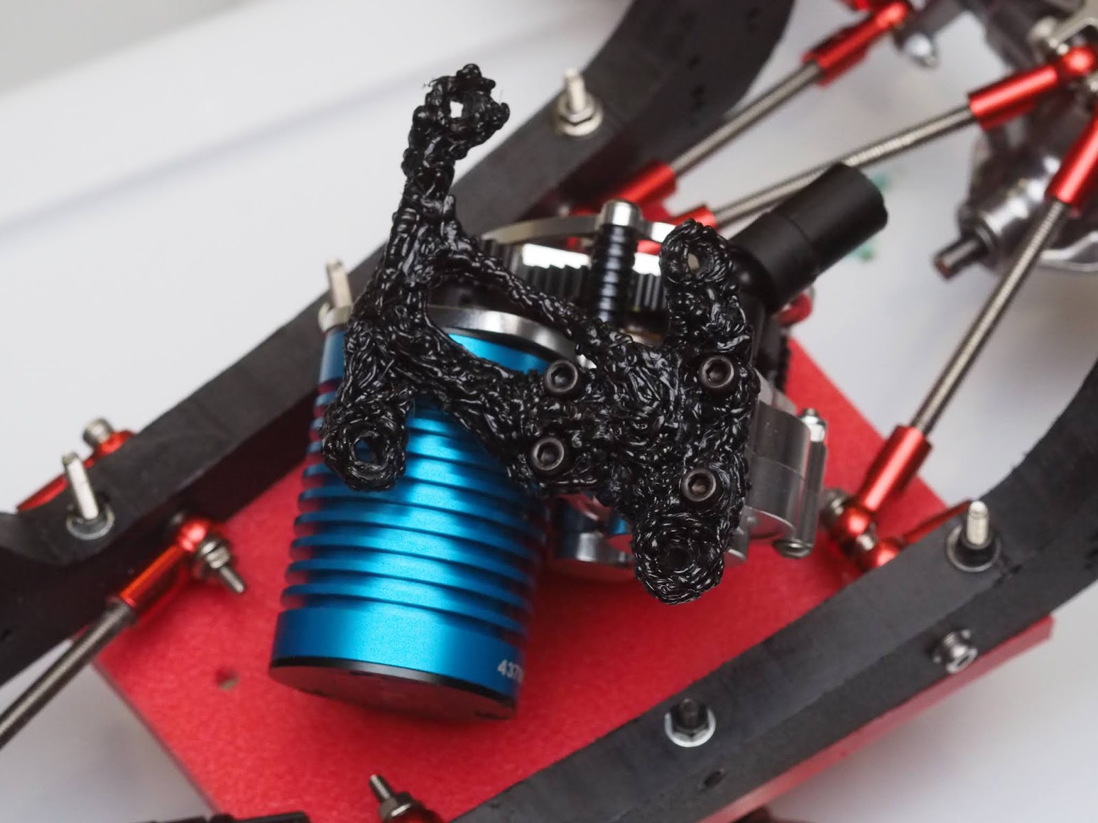
As in a previous post, the transmission is held in place using a bracket, drawn by a 3d pen, and made of PETG. This is an experiment to see how it holds up. So far so good - though I may use Kydex next time. With the transmission and driveshafts mounted, getting the car running is a lot of finishing touches. How shall I mount the body? The battery?

I wanted to experiment more with kydex - Used in a previous RC car to make a battery cover. I wanted to make a platform for the battery which curved down and around the motor, gearbox and shafts.


I cut the sheet with my scrollsaw first - a rectangular piece with some tabs. I heated the piece over the stove until it went soft - Kydex is a thermoplastic. It's perfect for this. I was able to curve the kydex to fit perfectly, offering a place to mount batteries and electronics and keeping out dust too.

Finally it's time to put on body posts to mount the body. In the front I used 1/4" HDEP. I used kydex to make a hinge for the rear.


Here is is completed. The kydex in place holding 4 18650 cells. I was testing the cells in here so I ran it with a data logger. that's the black box on top the green batteries with the blue LCD.


The under-side of the car. You can clearly see the solid axles and 4 link setup. I swapped out the front locked diff for an open Axial differential. Obviously the aluminum axles aren't from Axial, but a generic Chinese company, but that's because my first set of Axial axles snapped and I just don't think they do well for bashing.

The car's body has a high back, and I didn't want to make tall posts in the rear. Instead I bent Kydex around 4mm threaded rod, and cut out the center of the piece making a hinge. This was bolted to the car and the body. Kydex is nice to work with - both cutting, and shaping with heat. It's pretty durable too. It's often used in knife holsters and comes in a variety of patterns.


Here's a view of the car from behind. The transmitter in the background is a Radiolink RC6GS. It's a 6 channel pistol grip transmitter. It comes with a receiver that has a gyroscope - so I may use it and turn this into a drift machine. With the locked rear differential and open front, the rear is easy to break free by stomping on the throttle in a turn. This view shows the rear bumper - the hinge that the body is attached to the car by.

Here's the front of Project Yellow. I added a red stripe to make it go faster. I don't think it worked, but it looks nice :)

Side profile. Considering using bigger wheels to make better use of the wheel wells.

Here it is with the body up, and the batteries still connected to the data logger. the foam used to pad the body posts is actually spare nerf darts ziptied to a cross bar. From testing the car under max acceleration on carpet (high traction) the peak current draw was 35Amps. This is pretty low for a 1/10 scale car, so there's room for more load - like bigger tires. The 18650s I'm using are Sony/Murata VTC5A cells. These cells can handle 35 amps each, and since I'm running them in parallel, we're looking at 70 amps maximum. 

I thought it looked a little bare so I added some detailing with vinyl, and some googly eyes as headlights of course. 

Future ideas:

  • Add mount for FPV camera. Not sure if I should make it inside or on the roof.
  • Bigger tires.
  • Maybe push the body back a little and give more room to the front wheels.
  • I'd like to try some 21700 cells, or even 26650s. If I can do 3s1p it will be a bit easier to manage.
  • Try using UHMW polyethylene again and compare to HDPE. HDPE is softer and more malleable, but I need to really put UHMW PE under some load testing again.

Update:
Pet-G brace shattered like glass after a rollover on concrete. Had to replace with kydex sheet - now I know that would be tougher. My guess is the filament absorbed moisture before use leading to a brittle part.
Never mind the comic book page I took the picture on. needed a light colored background and this was near. If Batman were driving this, it would fit :D

Friday, July 31, 2020

3d pens can be a useful tool.

Most people have heard of 3d printing, but what happens if you take the printer's extruder, add a pen like grip, get rid of the rest of the printer, and add portable or lower power cables? Now you have a 3d pen, much akin to a glue-gun for plastic.


Despite the name, a 3d pen is not going to let you draw in the air. You CAN pull up plastic from a point and wait for that stretch of plastic just formed to harden a little, then go back... It's not easy, it's not ideal. The 3d pen however is really good at laying down plastic on surfaces though. So if you want to draw in 2d over a paper design you drew, on glass of a silicone mat - you'll get a decent output. Then you can hold multiple 2d pieces together, and use the 3d pen to connect pieces using molten plastic like a glue.

The other really useful application is fixing things. broken pieces of plastic? Mend it! weak plastic arm? Use the pen to reinforce it. I've been using it for modifying toys - reinforce weak points, sometimes heavy modifications breaking parts off and adding back plastic using the pen in a different way.


My most recent usage has been with radiocontrol toys. Durability is an issue, especially impact and heat. ABS isn't a bad choice, but PET-G has more flex which lends it toughness. Nylon would be ideal, but it's more expensive, and You need need more temperature than pens allow to handle nylon. 250-260C is ideal, but my pen only gets to 230. I'm using PET-G.

I started with a WPL B1 - It's a non-hobby-class toy - initially. But with steel c-channel chassis rails, metal leaf springs, and lots of upgrades including metal axles, gears, shafts etc - it becomes hobby grade. The "servo" is a laughable thing. An all or nothing design consisting of a motor with an obstruction to act as end points. As a result, when turning, there's no proportional control, and the straining motor acts like a short reducing battery life and starving the motor of power. I used a soldering iron to melt away excess plastic to make room for a real servo. The pen was used to "draw" a bracket in place. The bracket goes around the existing screws and can be removed if I ever need to change to servo. This just took a few minutes.


For another example, I needed a bracket to hold a Axial SCX type transmission onto a car I've been working on. I needed a bracket because there wasn't room for it. The transmission would need to go in at an angle.


I started by drawing plastic around the screws in the base of the RC car, and plastic at the base of the transmission around the screws.


I held the transmission in place and connected the base of the transmission to the plastic around the bottom screws. It doesn't stick to metal screws, but it can take some wiggling. Here it is with the bottom 2 screws. 


Since space is limited, I can't even fit the pen where I need it. So I'm drawing plastic, Extending the base to a point I can get to. PS: that's a silicone coaster, not a floppy disk (though it is floppy).


I put the motor back on the 2 lower screws, and extend the bit I drew to connect to the other screws. After letting it cool and harden I pulled it off and reinforced the beams drawn.


Final product: The bracket is strong enough to take impacts. It hold the transmission in place firmly, while having a little give to dissipate energy of impacts. 


Notes:
It does look a little messy. These fixes aren't going to be that visible. That said, should a smoother look be required, practice does help - or use a soldering iron or wood burner to smooth the lumpy finish.

Wednesday, May 20, 2020

Odroid NAS died, Trying a Raspberry pi 4

My Odroid died over the weekend. It's been running every day for 4 years so, I guess it did OK doing what it wasn't really meant to do.


So I'll use something else not meant to do it again :D
This time a Raspberry Pi 4. USB 3 and gigabit ethernet.
https://magpi.raspberrypi.org/articles/raspberry-pi-4-specs-benchmarks


Using the Pi's Wifi:

beomagi@BeoBalthazar ~  2020-05-19 21:46:24
└─ $ ∙ iperf -c 192.168.1.42
------------------------------------------------------------
Client connecting to 192.168.1.42, TCP port 5001
TCP window size:  512 KByte (default)
------------------------------------------------------------
[  3] local 192.168.1.109 port 61000 connected with 192.168.1.42 port 5001
[ ID] Interval       Transfer     Bandwidth
[  3]  0.0-10.0 sec  91.2 MBytes  76.5 Mbits/sec

beomagi@BeoBalthazar ~  2020-05-19 21:46:45
└─ $ ∙ iperf -c 192.168.1.42
------------------------------------------------------------
Client connecting to 192.168.1.42, TCP port 5001
TCP window size:  512 KByte (default)
------------------------------------------------------------
[  3] local 192.168.1.109 port 61509 connected with 192.168.1.42 port 5001
[ ID] Interval       Transfer     Bandwidth
[  3]  0.0-10.0 sec  99.5 MBytes  83.4 Mbits/sec

2 runs showing this will generally be ~80 Mbps, so I can expect about 10 megabytes per second. It's not great, though it will handle HD videos (ish).
Benchmarking the wireless has not been great - so I'll have to hook it up to my router via gigabit ethernet.


Using the Pi's ethernet to my router, then over AC wifi:
Hooked up to my AC router, via gigabit ethernet, my PC over AC is getting much better bandwidth.


Using the Pi's ethernet to my router, then over AC wifi:

beomagi@BeoBalthazar ~  2020-05-19 22:07:18
└─ $ ∙ iperf -c 192.168.1.42
------------------------------------------------------------
Client connecting to 192.168.1.42, TCP port 5001
TCP window size:  512 KByte (default)
------------------------------------------------------------
[  3] local 192.168.1.109 port 49435 connected with 192.168.1.42 port 5001
[ ID] Interval       Transfer     Bandwidth
[  3]  0.0-10.0 sec   468 MBytes   392 Mbits/sec

beomagi@BeoBalthazar ~  2020-05-20 12:57:16
└─ $ ∙ iperf -c 192.168.1.42
------------------------------------------------------------
Client connecting to 192.168.1.42, TCP port 5001
TCP window size:  512 KByte (default)
------------------------------------------------------------
[  3] local 192.168.1.109 port 49454 connected with 192.168.1.42 port 5001
[ ID] Interval       Transfer     Bandwidth
[  3]  0.0-10.0 sec   483 MBytes   405 Mbits/sec

My HTPC is directly connected to the same router via cable, so pure wired numbers look excellent.
Downloading files are near 50MB/s so this is quite nice.


Using the Pi's purely over gigabit ethernet:

beomagi@beo-htpc ~  2020-05-20 13:11:17
└─ $ ∙ iperf -c 192.168.1.42
------------------------------------------------------------
Client connecting to 192.168.1.42, TCP port 5001
TCP window size:  604 KByte (default)
------------------------------------------------------------
[  3] local 192.168.1.108 port 54694 connected with 192.168.1.42 port 5001
[ ID] Interval       Transfer     Bandwidth
[  3]  0.0-10.0 sec  1.10 GBytes   943 Mbits/sec

beomagi@beo-htpc ~  2020-05-20 13:17:44
└─ $ ∙ iperf -c 192.168.1.42
------------------------------------------------------------
Client connecting to 192.168.1.42, TCP port 5001
TCP window size:  408 KByte (default)
------------------------------------------------------------
[  3] local 192.168.1.108 port 54706 connected with 192.168.1.42 port 5001
[ ID] Interval       Transfer     Bandwidth
[  3]  0.0-10.0 sec  1.09 GBytes   940 Mbits/sec

Now we're talking. This should be good for ~115MBps


Bottleneck - harddrive:

pi@raspberrypi:~/shares/major $ dd if=/dev/zero of=./testfile bs=1000M count=1 oflag=direct
1+0 records in
1+0 records out
1048576000 bytes (1.0 GB, 1000 MiB) copied, 10.8304 s, 96.8 MB/s
pi@raspberrypi:~/shares/major $  dd if=./testfile of=/dev/null bs=1000M count=1
1+0 records in
1+0 records out
1048576000 bytes (1.0 GB, 1000 MiB) copied, 8.92268 s, 118 MB/s


These are directly on the pi, so they give a decent indication of that USB 3 capability with harddrive storage. It's not far off from the gigabit throughput so it's well matched. The numbers are actually slightly better than the odroid, which is excellent.

Previous NAS setup:
https://beomagi.blogspot.com/2016/09/odroid-xu4-my-new-nas.html